Leggy
The Legged Robot
Fall 2020

Overview
In Fall 2020, I decided to make my own legged robot as the final project for the Mechatronics Design class (ME102B) at UC Berkeley. The following is the overview video of the final prototype, which I designed and manufactured in two weeks. Please scroll down if you would like to know more about this project, see Gallery here.
About Leggy
Legged robots are used to reach out to places where usually 4-wheels cars cannot go. I am interested in working with robotics and this project is the combination between my curiosity for Internet of Things (IoT) and linkages design. The design was inspired by a product created by Wit Machine. My system is able to walk in different directions, its angular speed and direction can be controlled using the phone. In further applications, it is possible to install a camera in the front of the robot for exploration and it could also be a great toy for kids.
Leggy SOLIDWORKS simulation
I started my design process using SOLIDWORKS so that I could simulate how my robot was going to behave before manufacturing.
Electromechanical Details
Linkages:
All linkages were laser cut and the hinges where 3D printed as shown below. I put everything together using M4 screws, nuts, and washers.

Legged robot parts
The wheels are connected using a shaft and two collars.

Directional system & wheels
End-cap

Notice that it was necessary to add hot glue to the end of the nuts to prevent them from falling off or tighten up the mechanism, due to the high vibrations of the robot. In a future generation, a lock nut will be used.
Side view of DC motor and Motor Connectors
DC motor - legs:
The DC motor is stick to the center of mass of the vehicle and it is connected to the legs using the Motor Connectors as shown below. The Motor connectors are placed parallel to each other to allow the robot to create the walking movement when the shaft starts rotating.

Top View of DC and Motor Connectors

Side view of DC motor and Motor Connectors
Servo motor - direction:
After I had the legged robot walking, I noticed that it was necessary to add a way to control the direction. As I was short in time to manufacture a shaft that could control direction using the wheels. I decided to use a servo motor connected to a wooden stick and some silicon ends made of finger protectors. The way the direction control works is by moving the servo motor between 50° and 100° and this will allow the silicon end to push the wheel in the desired direction while the robot is walking.

Directional system
App interface:
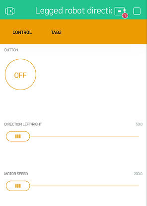
Blynk is a IoT platform that allowed me to control the legged robot with my phone using WiFi and the created interface is shown in the right. The first feature that I implemented was an on/off "Button." Additionally, the direction of the servo can be controlled by the second feature "DIRECTION LEFT/RIGHT" where 50° would allow the robot to move to the left and 100° to the right. The initial position of the servo motor in a straight path is 90°. Then, I mapped the maximum and minimum angular speed that the robot needs to walk using the third feature "MOTOR SPEED" as a potentiometer. The maximum and minimum pulse-width modulation (PWM) commands are 250 and 200, respectively.

Blynk interface & controls for the legged robot
Demo - Blynk interface & controls for the legged robot
Circuit
There are four main components for the circuit:
-
ESP32: The ESP32 (Assembled Adafruit HUZZAH32 – ESP32 Feather Board - with Stacking Headers, $21.95) is the microcontroller for the system. It controls all the electronic components of the system and allows the connection to the phone.
-
Dual motor driver: The DRV8833 Dual Motor Driver Carrier (DRV8833 Dual Motor Driver Carrier, $4.95) allows to control the direction and angular velocity of the DC motor via PWM signal from the ESP32.
-
Servo motor: I had this old servo motor (Lewansoul 9G Servo Micro servo Metal Gear Motor Anti Blocking servo (1PC), $8.99) to change the direction of the wheels so that the legged robot can go to different direction.
-
Double shaft DC motor: I got this double shaft DC motor (Antrader Gear Motor Dual Shaft 3-6V TT Motor for Smart Car Robot Pack of 6 (I Shape), $1.50/each) to be able to move the legs of the robot.
In addition to these parts, I also got some small breadboard (MCIGICM 6PCS 170 tie-Points Mini Breadboard for Arduino, $0.99/each) to have a more compact circuit. The circuit is powered by a 9V battery that is connected to the motor driver and a 3.7V Lithium Ion Polymer (LiPo) battery to power the microcontroller and the servo motor.

Circuit Diagram
Finite State Machine
The system can be moving and changing direction at the same time. Therefore, "Legs moving" and "Turning" left/right are independent of each other. The directional mechanism depends on position (angle) input and the legs moving depend on the PWM input.


